This course is run at the The University of NottinghamĀwithin the School of Computer Science & IT. The course is run by Graham Kendall (EMAIL : gxk@cs.nott.ac.uk)
In all the discussions above we have mainly looked at the operating system from an outside view. In this section we look inside the operating system to see the various ways they can be structured.
One way an operating system can be structured is not to have a structure at
all. That is, the operating system is simply a collection of procedures. Each
procedure has a well defined interface and any procedure is able to call any
other procedure.
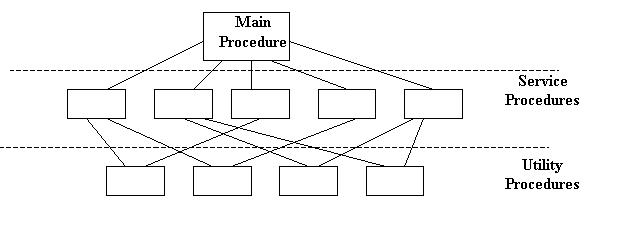
The operating system is constructed by compiling all the procedures into one huge monolithic system. There is no concept of encapsulation, data hiding or structure amongst the procedures.
However, you find that the way the system procedures are written they naturally
fall into a structure whereby some procedures will be high level procedures
and these will call on other utility procedures.
This diagram shows this structure. The main procedure is called by the user programs. These call the service procedures which, in turn call on utility procedures.
|
In 1968 E. W. Dijkstra and his students built an operating system that was
structured into layers.
It can be viewed as a generalisation of the model shown above, but this model had six layers.
Layer 0 was responsible for the multiprogramming aspects of the operating system. It decided which process was allocated to the CPU. It dealt with interrupts and performed the context switches when a process change was required.
Layer 1 was concerned with allocating memory to processes.
Layer 2 deals with inter-process communication and communication between the operating system and the console.
Layer 3 managed all I/O between the devices attached to the computer. This included buffering information from the various devices.
Layer 4 was where the user programs were stored.
Layer 5 was the overall control of the system (called the system operator)
As you move through this hierarchy (from 0 to 5) you do not need to worry about the aspects you have "left behind." For example, user programs (level 4) do not have to worry about where they are stored in memory or if they are currently allocated to the processor or not, as these are handled in level 0 and level 1.
Virtual machines mean different things to different people. For example, if you run an MS-DOS prompt from with Windows 95/98/NT you are running, what Microsoft call, a virtual machine. It is given this name as the MS-DOS program is fooled into thinking that it is running on a machine that it has sole use of.
ICL's mainframe operating system is called VME (Virtual Machine Environment). The idea is that when you log onto the machine a VM (Virtual Machine) is built and it looks as if you have the computer all to yourself (in an abstract sense - nobody really expects to have an entire mainframe to themselves).
Both of these (Windows 95/98/NT and VME) are fairly recent developments but
one of the first operating systems (VM/370) was able to provide a virtual machine
to each user. In addition, each user was able to run different operating systems
if they so desired. This is a major achievement, if you think about it, as different
operating systems will access the hardware in different ways (to name just one
problem).
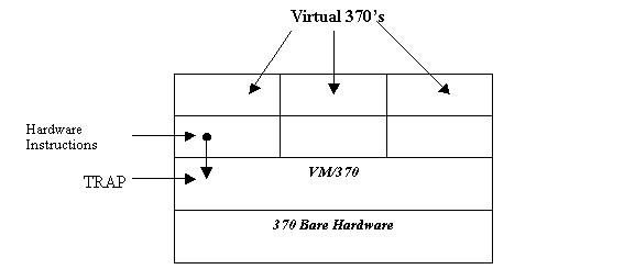
The way the system operated was that the bare hardware was "protected"
by VM/370 (called a virtual machine monitor). This provided access
to the hardware when needed by the various processes running on the computer.
In addition, VM/370 created virtual machines when a user required one. But,
instead of simply providing an extension of the hardware that abstracted away
the complexities of the hardware, VM/370 provided an exact copy of the hardware,
which included I/O, interrupts and user/kernel mode.
Any instructions to the hardware are trapped by VM/370, which carried out the instructions on the physical hardware and the results returned to the calling process.
The diagram below shows a model of the VM/370 computer.
 |
One of the recent advances in computing is the idea of a client/server model.
A server provides services to any client that requests it. This model is heavily
used in distributed systems where a central computer acts as a server to many
other computers.
The server may be something as simple as a print server, which handles print requests from clients. Or, it could be relatively complex, and the server could provide access to a database which only it is allowed to access directly.
Operating systems can be designed along similar lines. Take, for example, the
part of the operating system that deals with file management. This could be
written as a server so that any process which requires access to any part of
the filing system asks the file management server to carry out a request, which
presents the calling client with the results.
Similarly, there could be servers which deal with memory management, process scheduling etc.
The benefits of this approach include
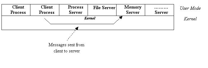
· It can result in a minimal kernel. This results in easier maintenance as not so many processes are running in kernel mode. All the kernel does is provide the communication between the clients and the servers.
· As each server is managing one part of the operating system, the procedures can be better structured and more easily maintained.
· If a server crashes it is less likely to bring the entire machine down as it won't be running in kernel mode. Only the service that has crashed will be affected.
The client-server model can be represented as follows
 |
| Last Page | Back to Main Index | Next Page |
ĀLast Updated : 08/01/2002